Installing Ruby in a Merlin
|
Overview
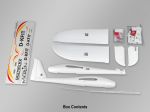
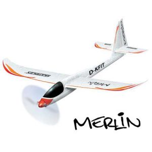
Here are instructions, including videos and high definition closeup pictures, for installing Ruby in the Multiplex Merlin. For installation in other aircraft, refer to Supported Aircraft to see if specific instructions may exist. Refer to the General Installation Instructions for planes not on that list, and for more detail about some of aspects of installation shown here.
If you have purchased a "ready to fly" Merlin, you can skip to "Getting Everything to Fit" below.
The only modification you will have to make to the Merlin airframe is the cutting out a small pocket on the right wing for the airspeed / magnetometer sensor, and the slicing of a channel for its ribbon cable.
A power sensor needs to be wired between the battery and ESC.
The only other special consideration is that Ruby and other plane components need to be inserted into the fuselage in specific order and locations in order for everything to fit in the small fuselage.
|
 Helpful things to do before assembling your Merlin Helpful things to do before assembling your Merlin
Ruby can be installed in a Merlin that has already been fully assembled, but if you have an unbuilt kit, the following will make installation easier:
- Leave the plastic cowling off of the right aileron servo. You will be running the airspeed cable underneath it before gluing it in place.
- If you plan to use a 2.4 ghz radio, create a hole in the back of the cockpit to allow the antenna to extend aft. [more info below...]
|
Mounting the airspeed / magnetometer sensor
Overview
The Ruby airspeed/magnetometer is required for Ruby operation. It must be located on a wing clear of propwash and magnetic distortion from servos. The sensor is embedded in a small pocket that you cut into the wing, similar to existing pockets for aileron servos. Mounting the sensor this way avoids adding significant drag, since nothing but the pitot tube extends into the airstream. The right wing is preferable only because of theleft-facing location of the ribbon cable connector on the sensor. |
 |
| |
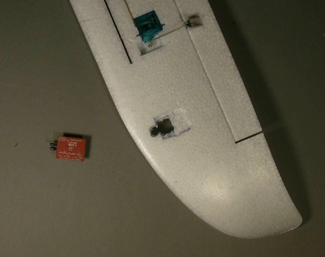
Cutting the pocket
You are going to be cutting a rectangular hole just big enough for the black box of the airspeed sensor. It will extend all the way from bottom to top surface of the wing. This will be similar to the holes that already exist in the wings for ailerons, but you'll also scoop out a wide, shallow indentation / shelf around that hole so that the rest of the sensor board can mount flush with the bottom of the wing. To avoid weakening the wing, all cutouts should be cut to fit the the sensor snugly, with no gaps which could allow flexing. |
| Note: Besides pictures below which can be clicked on to access large high resolution closeups, we've posted a high definition video of the cutting process: |
[Click here] to see the video at "fast forward" speed.
[Click here] to see the video at regular speed. |
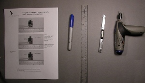
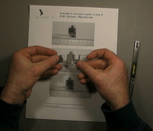
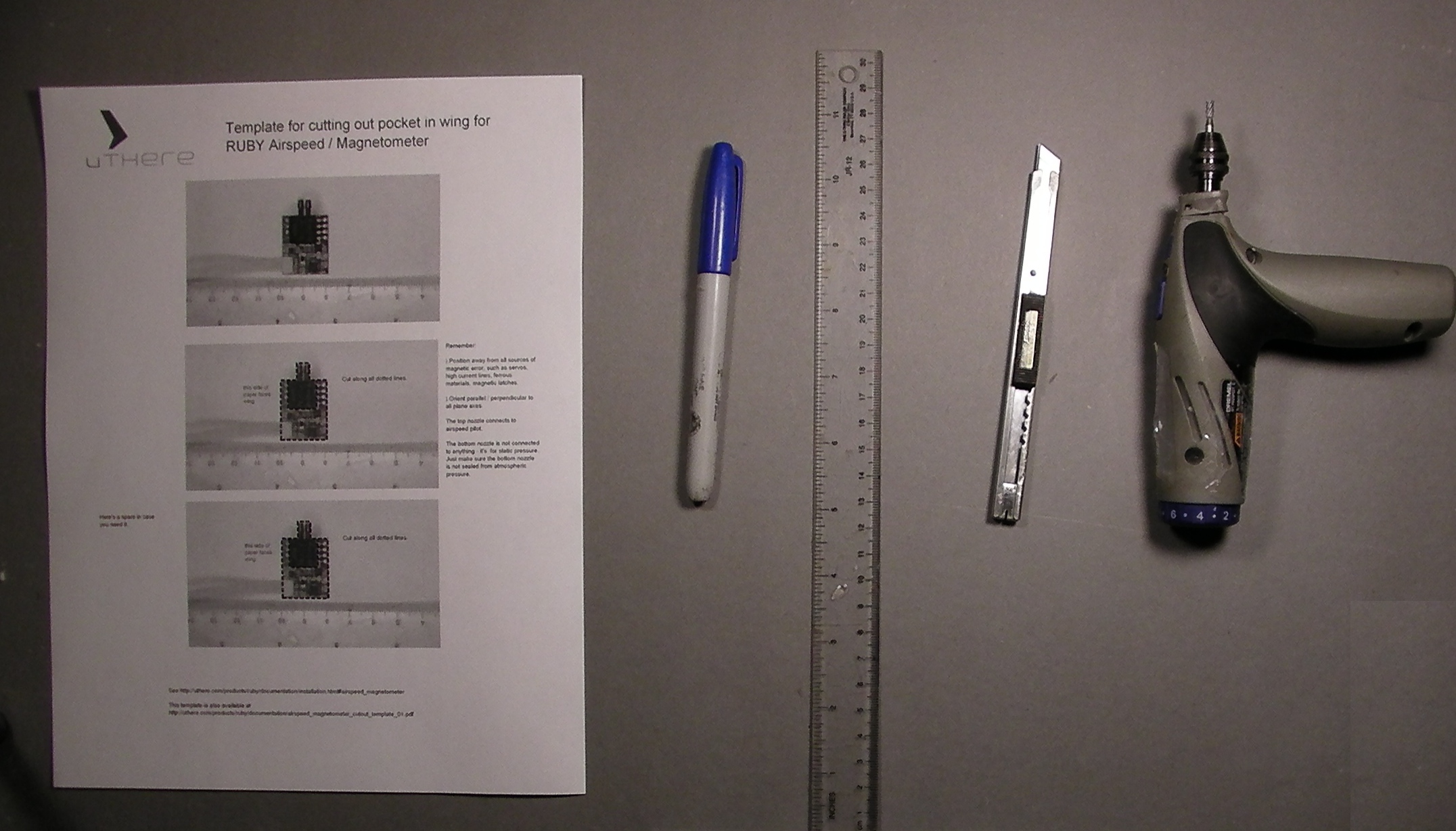
We've included in your kit a paper template that you can use to draw outlines for cuts you'll be making in the wing.
You can also download and print a fresh copy of the template from [here]. If you print this template yourself, compare the outline of the sensor to that printed on the sheet sure that the scale is correct.
|
click to enlarge |
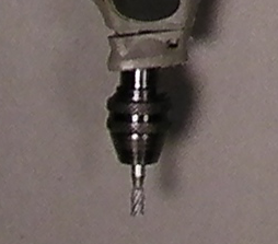
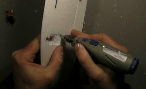
| A router bit mounted on a handheld Dremel tool will be best for the job of cutting holes and indentations in foam. |
 |
Cut out the template along all the dotted lines. You'll end up with a hole in the sheet and two smaller pieces of paper, one shaped like a "U". |
click to enlarge
|
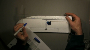
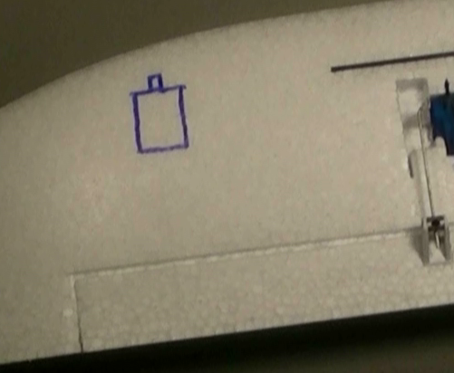
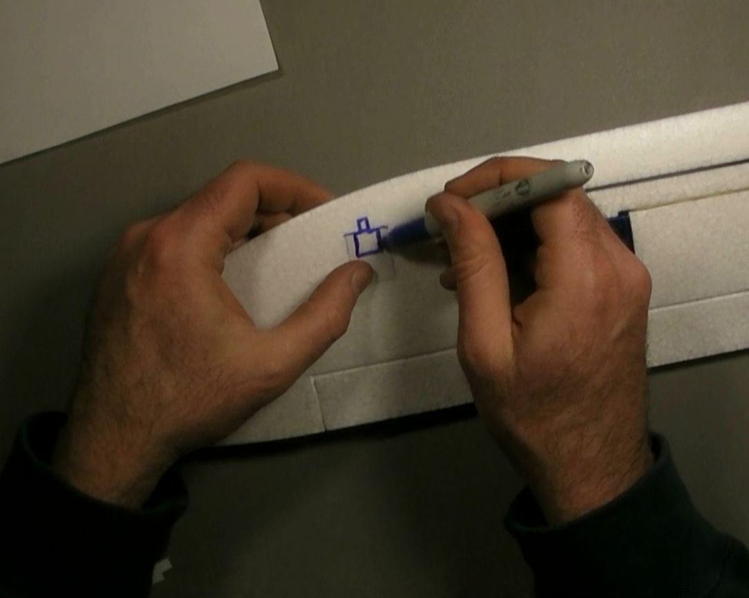
Take a ruler and line it up with the carbon spar. Seat it against the raised part of the wing near the root. Use a marker to draw a line that begins at 22 cm and ends at 24 cm.
Don't worry about having ugly ink on your wing. If you follow the instructions below carefully, you'll only end up with ink on portions of the wing that will be scooped away. |
click to enlarge |
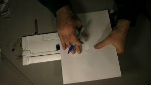
Place the template sheet on the wing with the print facing down on the wing.
Align the forward edge of the hole lined up with the line that you just drew. |
click to enlarge |
| Draw along the inside of the hole template to complete the outline of the sensor board and airspeed nozzle. |
click to enlarge |
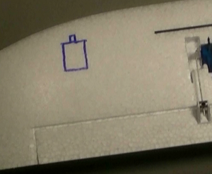
| Place the "U" shaped piece of template with print side facing down on the wing, fitting it on the outline you just drew. Use it to draw a 'U' shaped line which will complete the outline of the deep cutout you'll make for the black airspeed sensor component. |

click to enlarge |
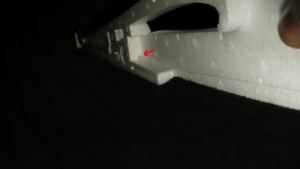
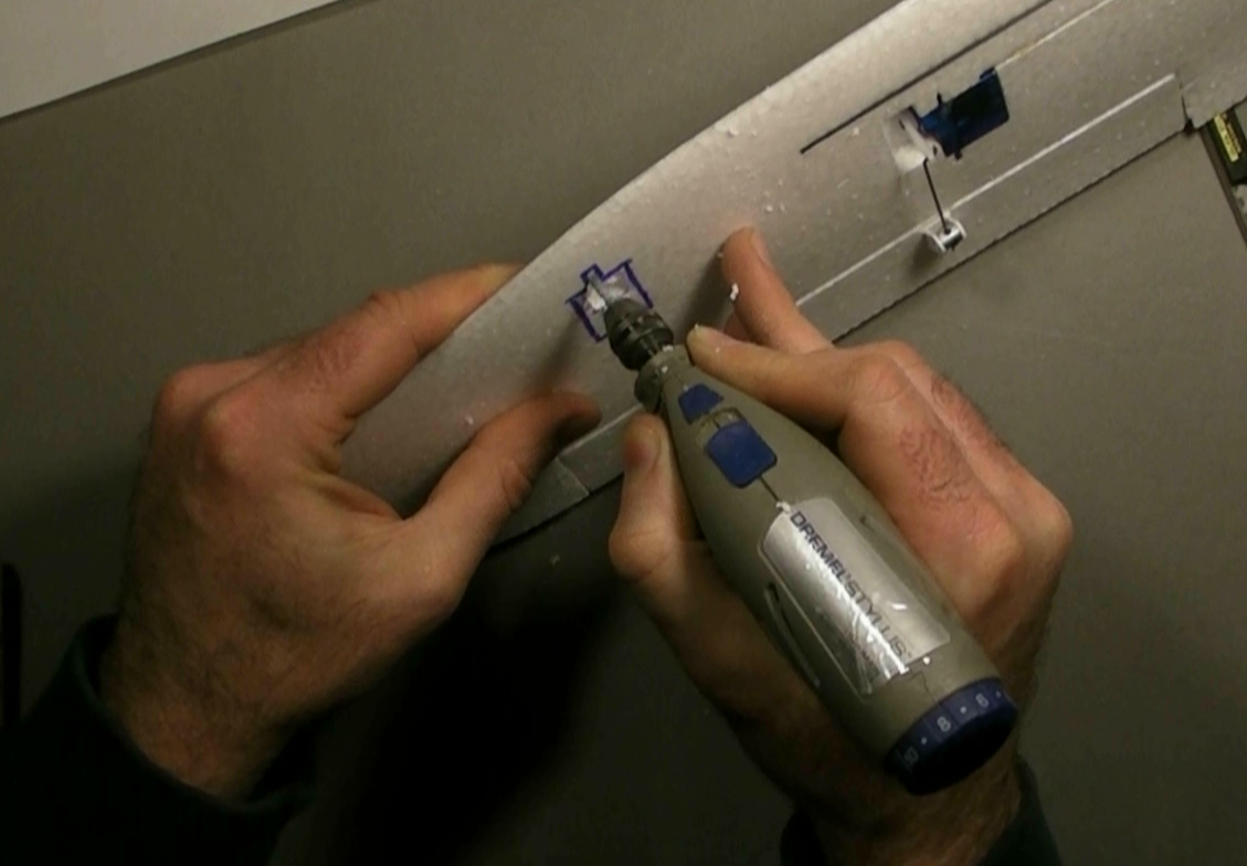
Use a dremel tool with router bit attached to carefully create the hole for the black box portion of the sensor that goes all the way through the wing.
IMPORTANT: Don't cut all the way through the wing for the entire board outline. Just cut the inner outline, roughly 15mm square, that corresponds to the protruding black box portion of the sensor, and cut a knotch for the airspeed sensor nozzles.
Remember that a snug fit with the sensor will give the wing more strength. Be careful not to make the hole any larger than the ink line that was drawn. Periodically trial-fit the airspeed sensor as you clear the hole.
|

click to enlarge |
Clear out foam about 1.5mm deep from the remainder of the board outline. You'll have to create small indentations in some places for some of the components on the sensor board. Again, periodically trial-fit the sensor to see where more foam needs to be cleared and to assure snuggest fit.
|
click to enlarge |
| |
|
Cutting the channel for the cable |
|
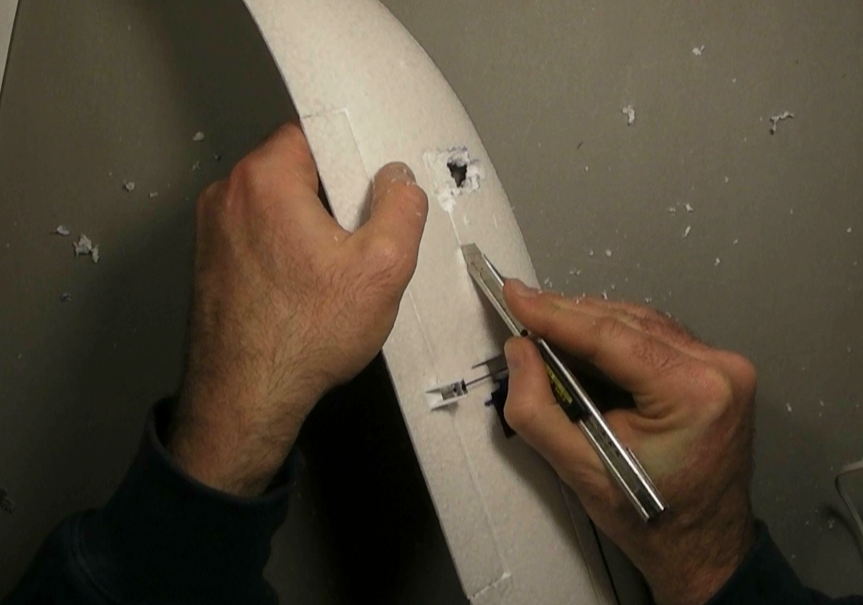
Use a sharp knife to cut a shallow channel running from the airspeed / magnetometer cable connector to the channel that already exists for the servo wires. Make the cut only as deep as the 5-wire cable is wide (3mm).
If you are modifying a Merlin that has already been completely assembled, you'll need to temporarily remove the plastic aileron cowling so the airspeed sensor cable can be rounted underneath the front of it. |

click to enlarge |
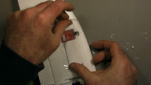
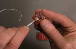
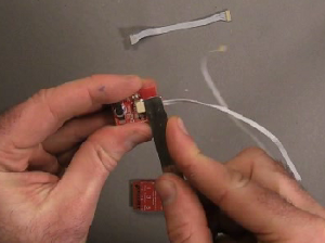
Plug the 5-wire ribbon cable into the airspeed / magnetometer sensor. (Press against the top edge of the connector with a wide screwdriver blade for full insertion.)
Insert the sensor into its place in the wing.
Make sure that mouth of the bottom port of the airspeed sensor is not pressed against foam in a way that would seal it from ambient air pressure.
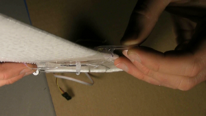
Tuck the cable into its channel up to the channel for the servo cable. You might use something like a butter knife to assist.
Tuck the cable in alongside the servo cable. It's easiest to remove the servo cable from its channel, then tuck the two in together.
|

click to enlarge
|
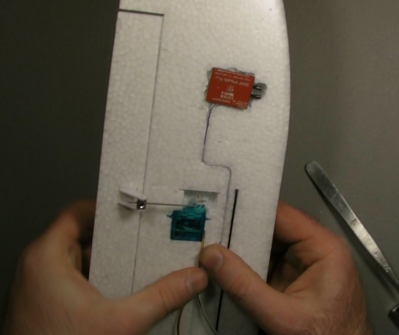
Apply a piece of wide packing tape to the bottom of the sensor and surrounding wing. Besides holding the sensor in place and allowing for easy access, this is important to restore strength to the wing. It also provides smoother airflow over the sensor and indentations.
** Poke a hole in this tape below the airspeed sensor nozzles to ensure that the sensor will be exposed to outside static air pressure and not enclosed in an airtight chamber. |
click to enlarge |
| |
|
Attaching the pitot tube
|
|
| Note: In addition to the pictures below, a high-definition video is available. |
[Click here] to see the video at "fast forward" speed.
[Click here] to see the video at regular speed. |
Rather than use a hard pitot tube which can snag on obstacles and cause damage, the pitot tube used by Ruby is a 1/8'' diameter clear piece of semi-flexible PVC tubing that is made just stiff enough with hot glue at the base to avoid flexing during flight.
Slide one end of pitot tubing to the top port of the airspeed sensor. Note that the tubing provided is slightly flanged at one end to fit over the nozzle.
Use dremel tool if necessary to make a slight indentation on top of wing to allow the tube to project straight forward, parallel to the wing bottom. |
click to enlarge |
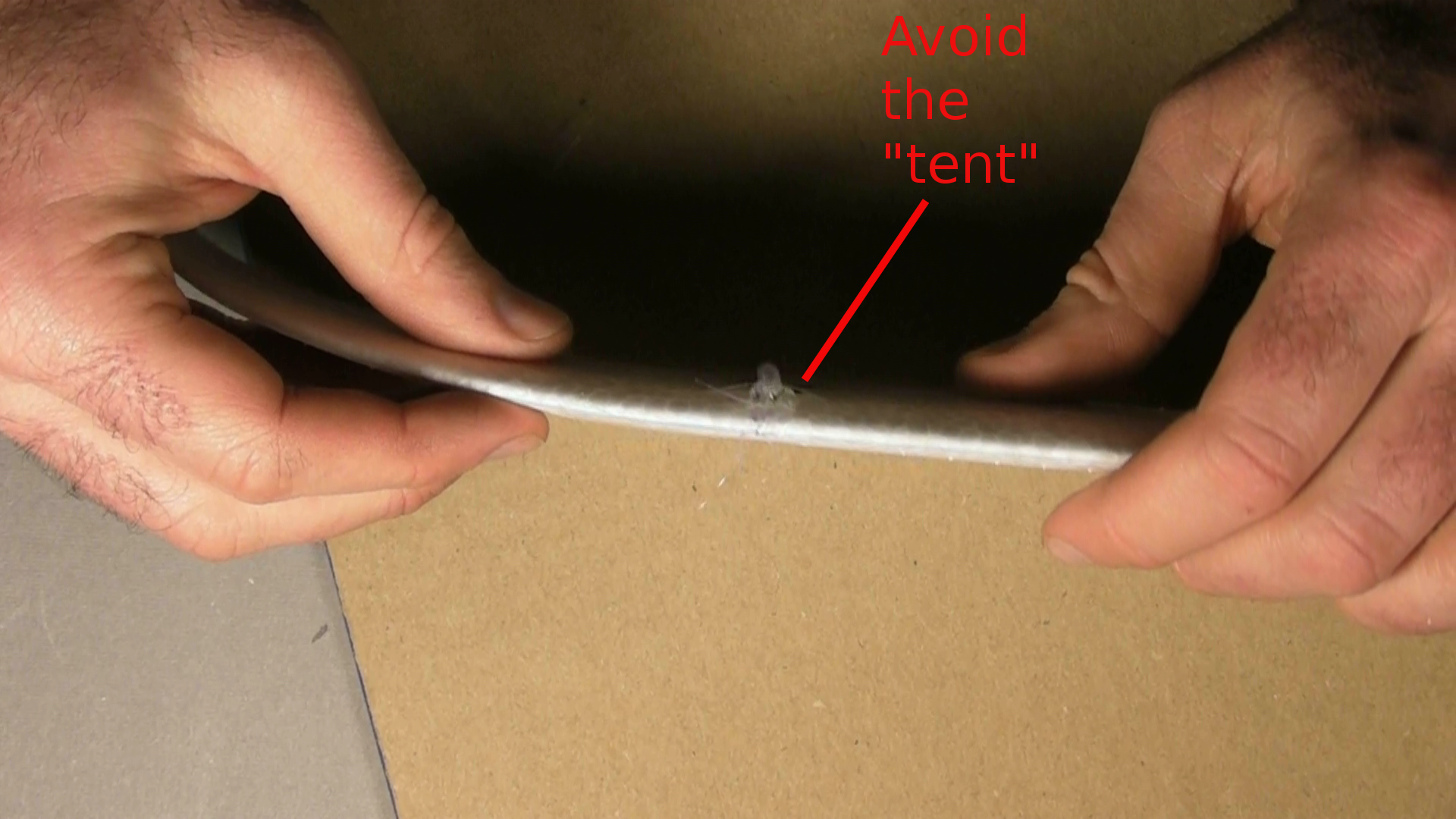
Apply packing tape to the sensor top surrounding wing up to the base of the pitot tube.
|
|
| ** Tuck or cut the tape around the airspeed tube to be sure that it does not have a tent-like opening that faces or "scoops" air from the oncoming airstream. Such an opening could pressurize the airspeed sensor chamber in flight with "ram" air pressure, leading to inaccurate low airspeed readings and poor IMU performance. |

click to enlarge |
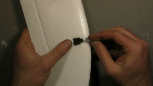
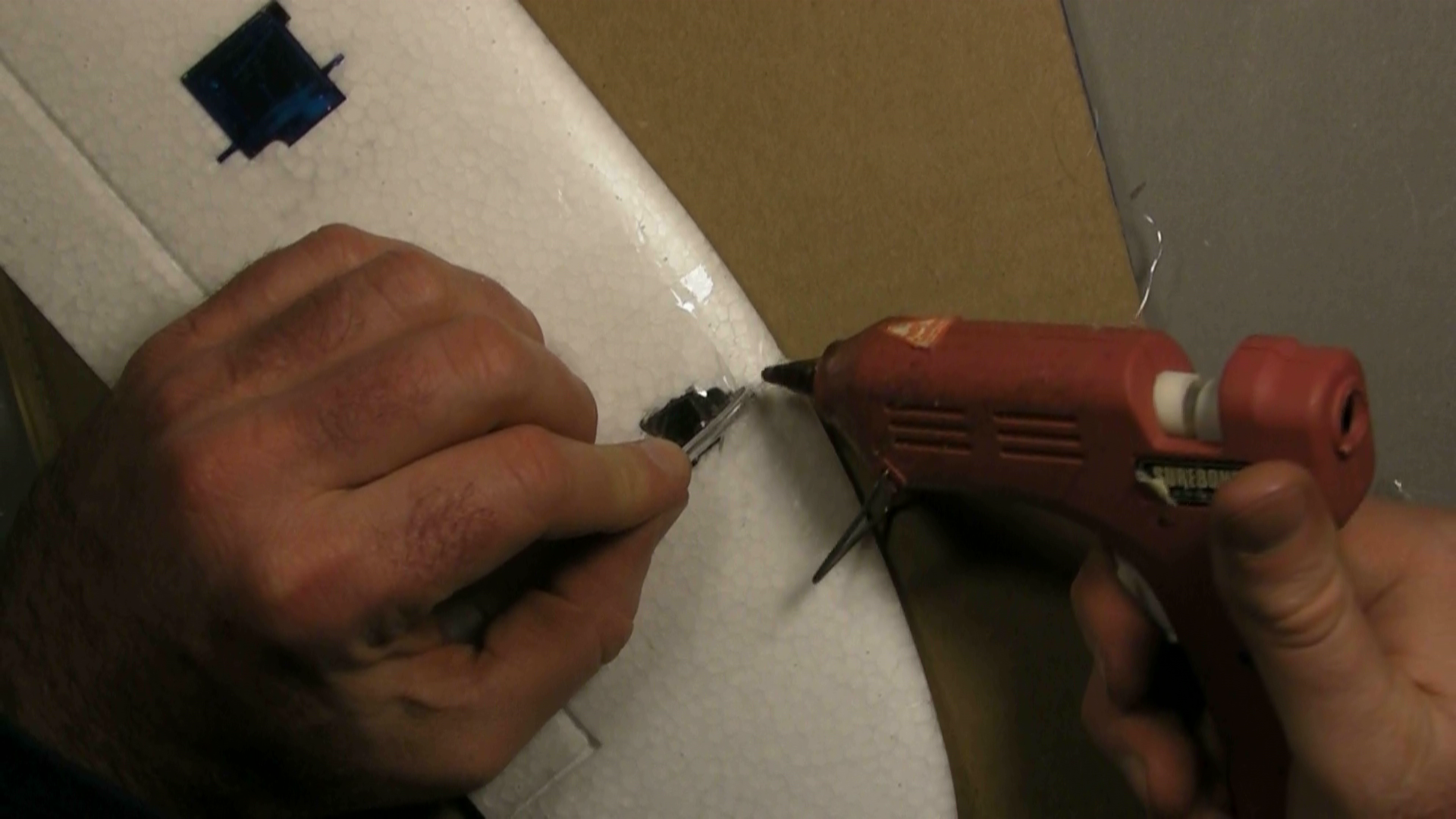
Hot glue is used to provide support and stiffening of the tube base to ensure that it always extends into the airstream parallel to the bottom of the wing.
Lift the pitot tube from the wing (but don't unplug it it from the airspeed sensor), and apply hot glue on the wing beneath.
Lower the tube onto the glue, and move side to side and twist back and forth so that the glue wraps around the tube and forms a base around it.
Apply a little more glue to the top of the tube to ensure that the glue completely encircles the tubing at its base, thus holding the tube mechanically rather than purely by adhesion.
|

click to enlarge |
As the glue cools, hold the tubing out at so that it is parallel to the bottom of the wing and to the plane fuselage, and will thus point directly into airstream during normal cruise flight. The glue should form a kind of "pylon".
You might add additional hot glue after the original glue cools to form a stronger base. |
click to enlarge |
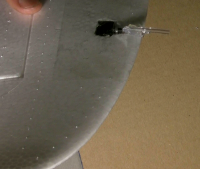
Trim the pitot tube so that just 20 mm extends beyond the leading edge of the wing.
Be sure to cut the tubing square, so that the face of the tube will be perpendicular to airflow.
|
|
|
Wiring the power sensor and switching regulator
Overview
Ruby currently requires a power sensor to enable it to control motor power with precision and track remaining battery capacity. You can fly Ruby without it connected, but you'll lose altitude hold, autonomous landing, and battery gauge capabilities.
We also recommend using a "Switching BEC" to power Ruby. See input power requirements.
To conserve space when installing in smaller planes, it's recommended that these parts be soldered together rather than add the bulk of additional connectors. |
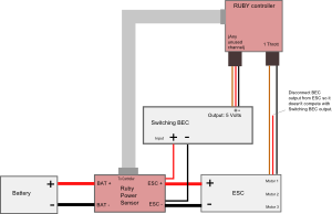
Schematic
|
click to enlarge
|
Soldering step-by-step: |
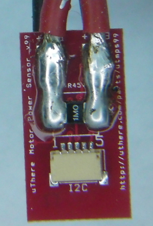
The wide copper traces through which power flows on the motor power sensor board are not sufficient to carry high current by themselves. They need a thick layer of solder on top of them to increase conductivity. Otherwise, at high power the traces can overheat and "blow" like a fuse.
Apply solder generously to cover the traces completely from the "BAT+" and "ESC+" pads all the way to each terminal of the power sense resistor. Generous solder on the power sense resistor terminals will reduce chances of it overheating and becoming inaccurate. It's ok if you get solder on top of the terminals.
|
click to enlarge |
Also be sure to apply extra solder to cover the short copper trace between "BAT-" and "ESC-" on the flipside of the sensor. |
click to enlarge
|
Strip just a little bit of insulation from the end of the positve ESC power input lead and solder to the pad marked "ESC+" on the Ruby power sensor module. Solder in a position such that the uninsulated portion of the wire doesn't extend close to the edge of the board where it could short with the "ESC-" wire that will be soldered to the opposite side.
Likewise, strip and solder the negative ESC power input lead to pad marked "ESC-" the opposite side of the Ruby power sensor.
Likewise, strip and solder the pieces of wire that were cut from the ESC to the pads marked "BAT+" and "BAT -".
If a battery connector was not already attached to those wires, solder one on. Even with a small plane like the Merlin, typical motor power is 2 - 4 amps with 8 amp peaks, so we prefer larger connectors such as Dean's "T" plugs.
Solder the positive power input wire of the switching BEC in with the positive power input wire of the ESC at the "ESC+" pad on the Ruby power sensor.
Solder the negative power input wire of the switching BEC in with negative power input wire of the ESC at the "ESC-" pad on the Ruby power sensor.
*** Be sure that no uninsulated portions of wires extend beyond the edge of the Ruby power sensor. In other words, be sure that there's no way that + and - leads could possibly short if the cables are twisted in any way. |
click to enlarge |

click to enlarge |
click to enlarge |
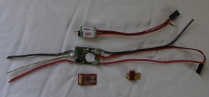
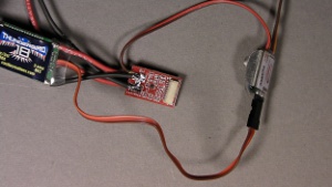
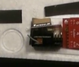
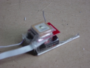
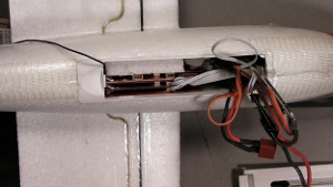
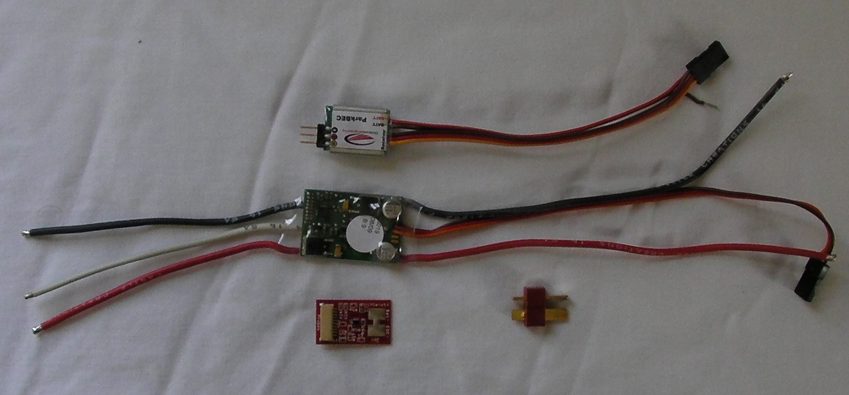
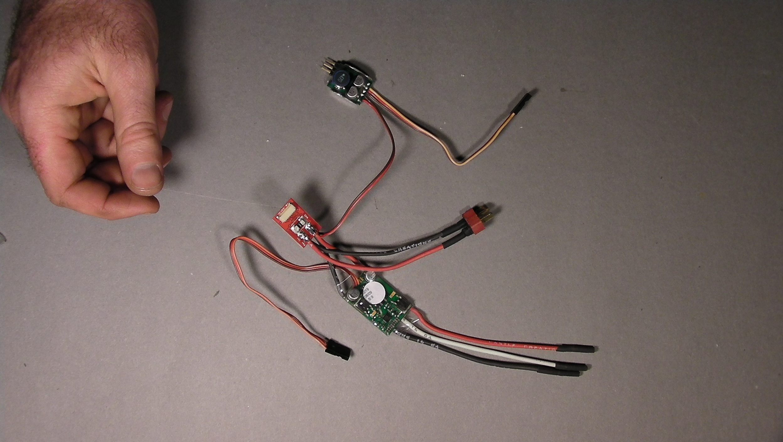
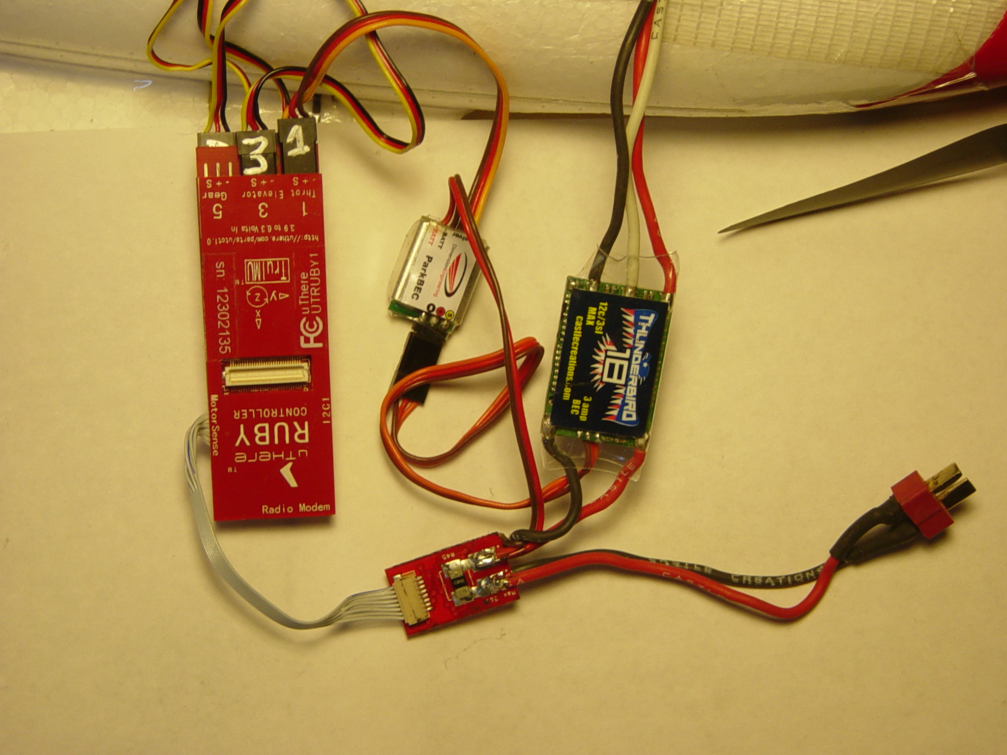
Here's what everything looks like when it's connected to Ruby,
(... except that the power sensor will be covered with electrical tape).
This picture is using a ParkBec, which combines power and throttle control into a single servo connector.
For other BECs, you'll have to plug the BEC power into an unused channel on Ruby separate from the throttle, or use a standard servo "Y" cable so the BEC can share a port with throttle or other servo. Be sure to disconnect the power wire coming in on the Throttle connector from the ESC so that the ESC's BEC and switching BEC are not trying to power the same electronics. |
click to enlarge |
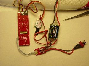
Cover all exposed metal contacts.
Wrap the power sensor in electrical tape or heat shrink tubing. For easier packing, tape the power sensor to the ESC to form a single bundle. Don't wrap tape around the ESC to the extent that it becomes thermally insulated and more susceptible to overheating. |
Keep switching BEC away from GPS and R/C receivers.
In our testing, we've found that the typical BEC needs to be at least 3 inches from GPS and R/C receiver.
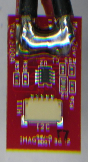
Note: The latest version of the motor power sensor connects to the connector labeled "I2C1" on the Ruby Controller. (Don't confuse with "I2C2" on the Expander.). The port labeled "Motor Sense" on the Ruby Controller is no longer used.
There are two connector labeled "I2C" on the power sensor. Either one can be used. The extra connector allows other I2C devices such as the airspeed/magnetometer to be daisy-chained.
|
Getting everything to fit
We've created a video showing most of the remaining steps in these instructions, including connection of all the cables and packing everything into the Merlin fuselage. |
[Click here] to see video at fast forward speed
[Click here] to see the same video at normal speed.
[Click here] to see a different video from a different angle. |
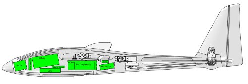
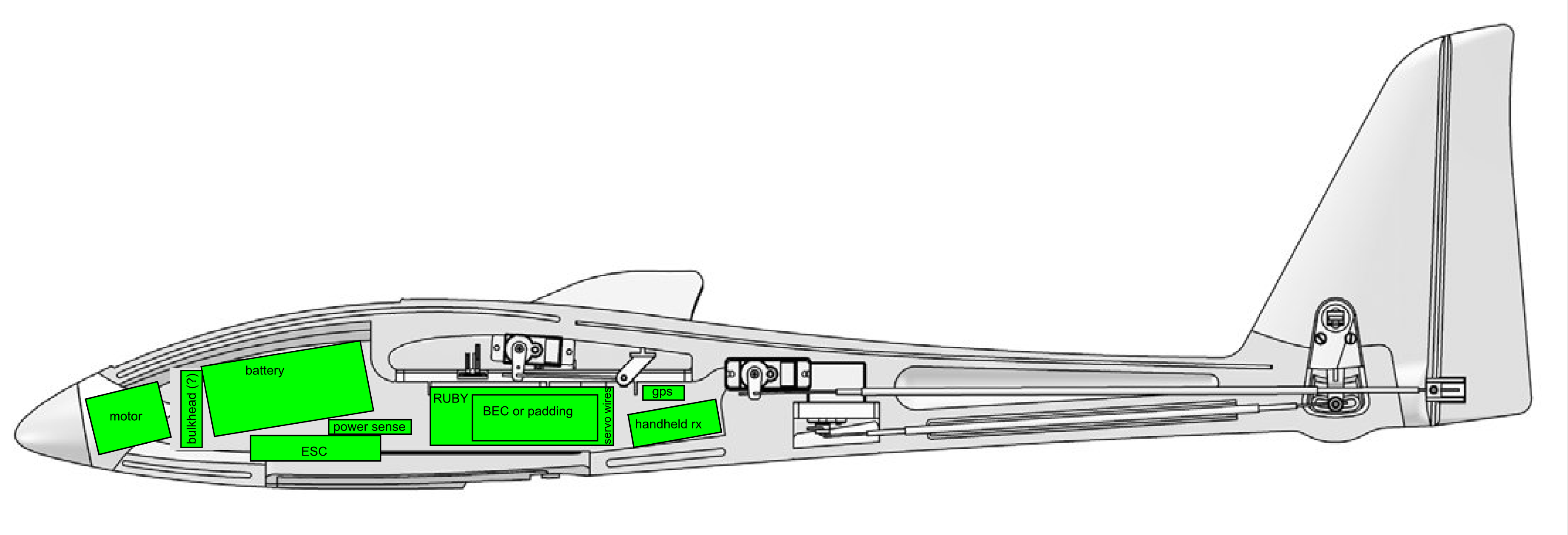
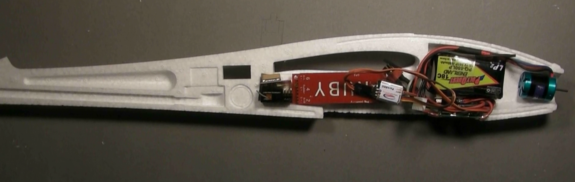
| A complete Ruby system, including Expander if desired, will fit along with other standard aircraft motor, electronics and a good sized battery, but everything must be inserted in a particular order and particular place, like a puzzle. |
click to enlarge |
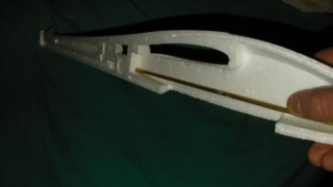
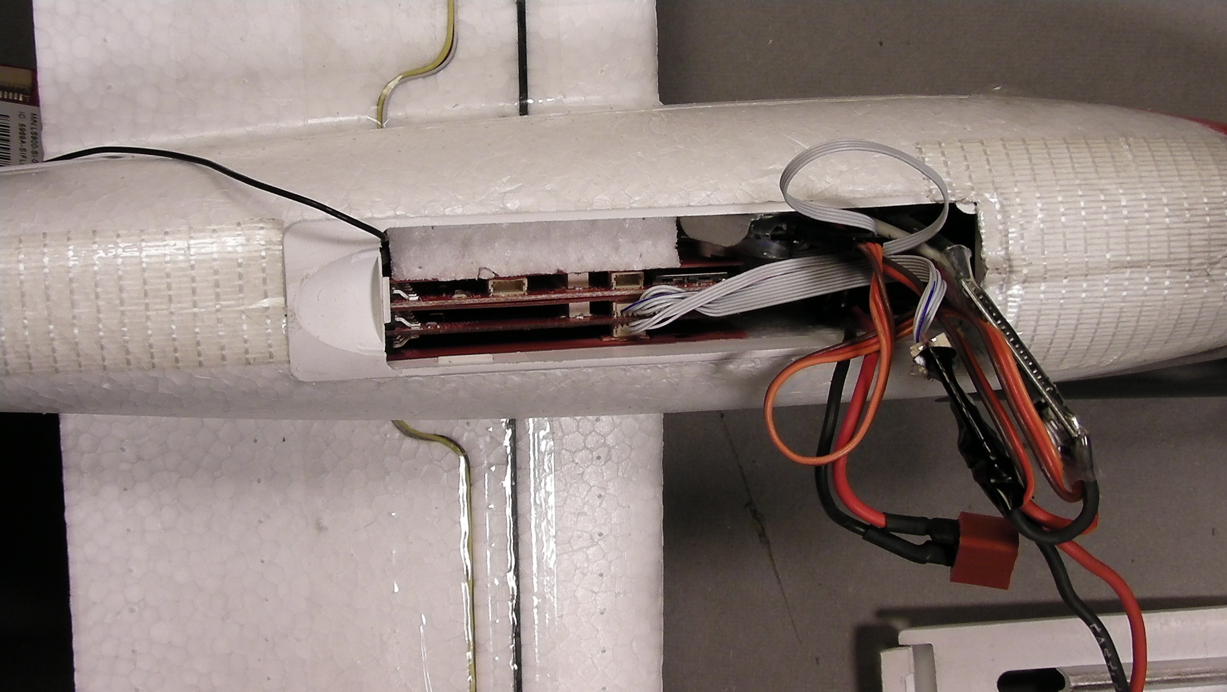
Here's a cutaway view of actual components in place.
Don't worry - you don't have to seal components into your Merlin before gluing the halves together. Everything can be inserted and removed through the hatch door. This image is just for illustration.
Note: Contrary to this picture, the face of the controller with large "RUBY" lettering should face the left side of the plane to match the orientation given in default configuration file that we provide for the Merlin. |
click to enlarge |
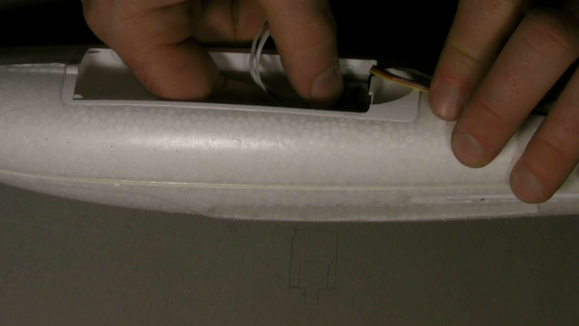
Plug in the wings
Run the servo and the thin grey airspeed/magnetometer cable through the round hole on the bottom of the wing cavity on the fuselage, then insert each wing into the cavity. A latching mechanism will engage. |
| |
Inserting GPS + Receiver |
First, we'll put the GPS and remote control receiver in the very back of the payload area.
|
|
If you're using a 72 mhz receiver:
The antenna can be run through the hole provided in the side of the fuselage, and in the tube that runs along the length of the fuselage. You can skip all the instructions below regarding a putting a hole in the back of the payload area. |
If you're using a 2.4ghz receiver:
Ideally, the antenna should be kept straight, and not tangled with other wiring or pressed against other components. |
|
Our strategy is to have the receiver antenna project into an 1/8'' diameter hole made in the bottom left corner of the back "firewall" of the payload area, extending under the rudder servo the length of the antenna. |
 |
If you purchased your Merlin kit from uThere, this hole will have already been made for you. Otherwise, you'll need to twist a piece of brass tubing with a sharpened lip to "core" it out.
If you have already assembled your Merlin, you'll probably have to remove the motor and use a longer brass tube inserted through spaces in the motor mount firewall to get the right angle. |
 |
| |
| The GPS module will sit on top of the receiver, facing up. The easiest way to get both into correct position is to tape them together before inserting into fuselage. |
Before taping them together, be sure to attach the receiver adapter and its cable. This is also a good time to check to be sure that the receiver is bound to your transmitter.
Also plug the 4 wire cable into the GPS module. |
click to enlarge |
To keep the antenna straight as it is inserted into the fuselage, tape a thin stick to the side of the receiver, and tape the antenna to the stick.
A little piece of the fiberglass rod left over from the original Merlin assembly is perfect. A thin dowel will also work. Do NOT use carbon fiber rod. |
click to enlarge |
| If you have a 2.4 ghz receiver with two antenna, they should be perpendicular to each other. SInce there's no room in the narrow payload area for the second antenna to extend out to the side, tape it to the side of the receiver so that it points vertically. The top of this antenna will be bent a little as it is inserted into the fuselage, but this will be better than just having it pressed against the side of the receiver parallel to the other antenna. |
click to enlarge |
| Now, tuck the bundle into the fuselage, probing the back firewall with the antenna stick until you find the hole that was made for it. |

click to enlarge |
| |
|
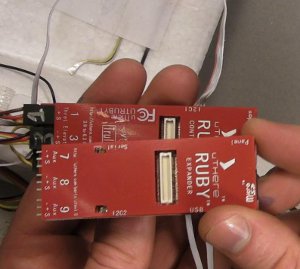
Connecting the Ruby Controller |
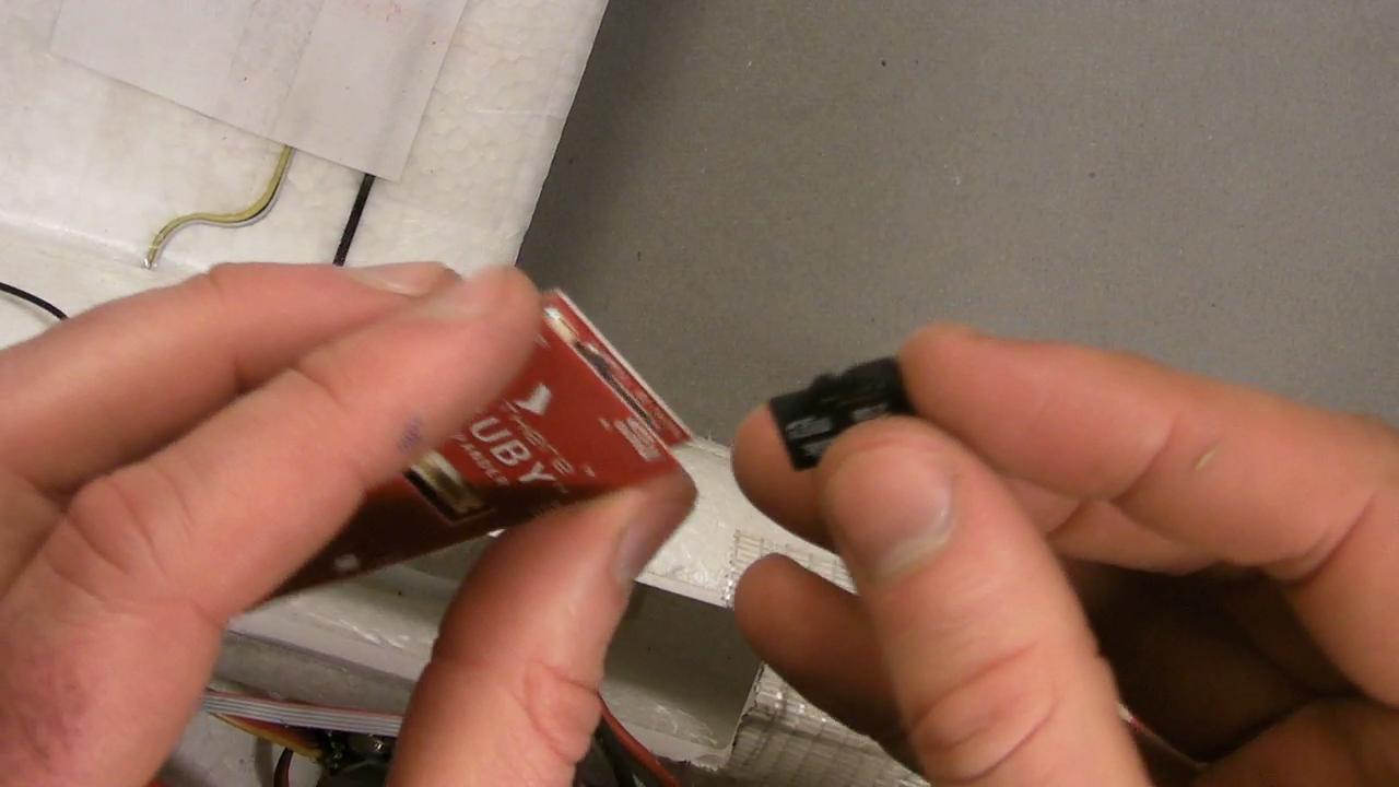
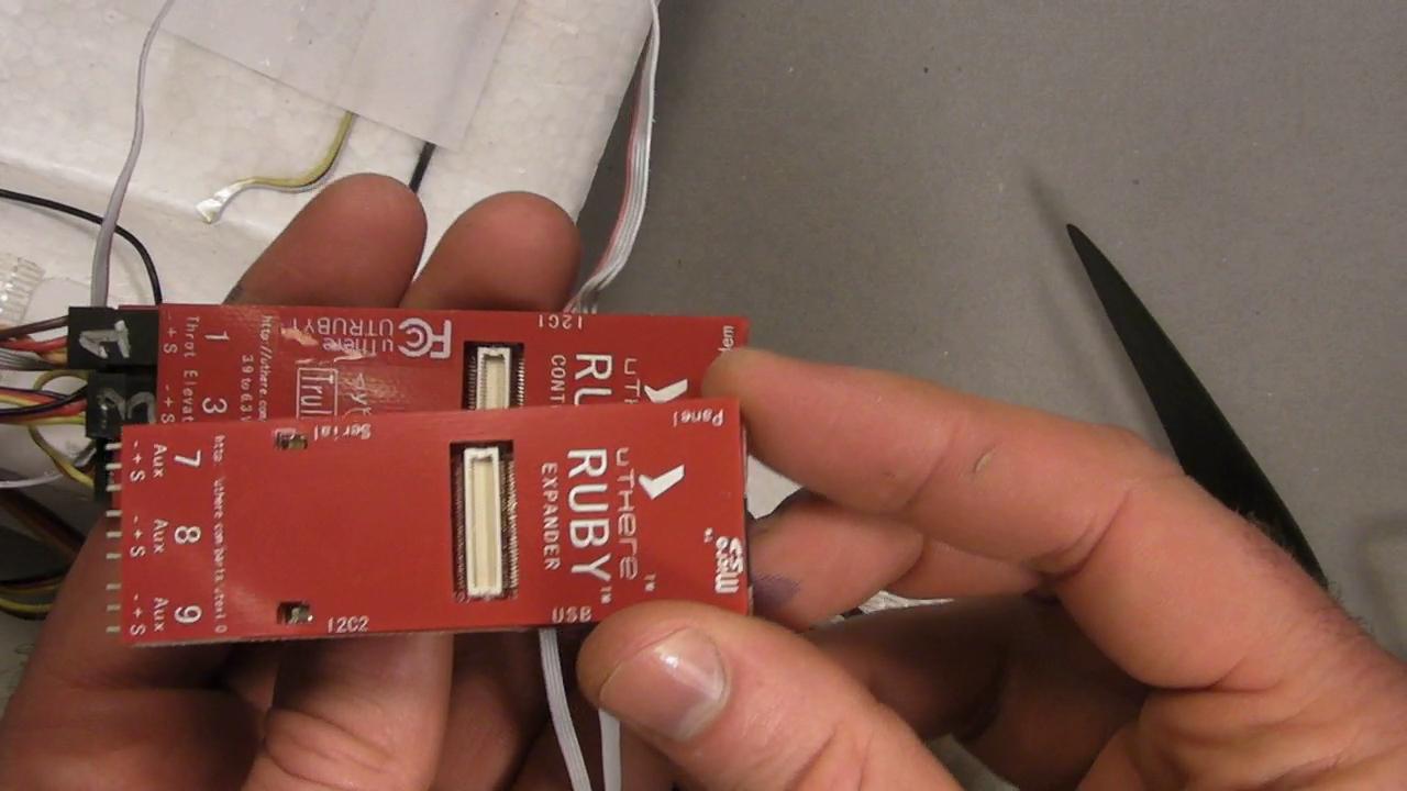
If you'd like to have flight data recording (and we recommend doing so whenever possible), insert your SD flash chip into the Expander, then plug the Expander into the Controller. Be sure that all the servo pins on the expander are facing in the same direction as those on the controller. Don't worry, there is enough room in the Merlin for the Expander.
The "expander spanner" is not necessary because you won't be using the servo channels on the Expander in the Merlin, so you can leave it out to save space.
Note that for flight data recording to occur, that SDflash chip must have a folder named 'ruby' with a file ending in ".UTMS" file on it. [more info..]
|

click to enlarge |
click to enlarge |
| |
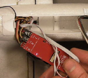
The Controller will be inserted into the payload area with the servo pins facing aft, and large "RUBY" lettering pressed against the left payload wall.
Hold it in this orientation as you begin to plug all cabling into the Ruby controller to minmize twisting of cables:
Servo connectors:
| Connect: |
to Ruby: |
Throttle
(and BEC if Parkbec) |
"1 Throt" |
BEC if not ParkBec
Empty otherwise |
"5 Gear" |
| Right Aileron |
"2 Ail R" |
| Left Aileron |
"6 Ail L" |
| Elevator |
"3 Elev" |
| Rudder |
"4 Rudd" |
All servo connectors on the controller (but not the Expander) are connected to the same 5 volt / ground power bus.
If you don't have a Parkzone BEC that feeds power through the throttle servo connector, you can plug it into channel 5 "gear", which is otherwise unused.
Be sure to plug servos and BEC into Ruby with correct polarity. Plugging the BEC in with polarity reversed could destroy your Ruby! Black wires should match with "-" printed on Ruby cover for every channel.
Ribbon cable connectors:
The ribbon cables currently don't have any markings on them, but you can identify them simply by counting the number of wires.
Motor power sensor
New version: 5 wire ribbon cable, connects to "I2C1" on Ruby Controller (not "I2C2" on Expander. "Motor Sense" connector is unused).
Old version: 8 wire ribbon cable, connects to "Motor Sense" on Ruby controller.
GPS (4 wire ribbon cable - there are two such cables in your kit. Choose whichever is the most suitable length)
Airspeed (5 wire ribbon cable).
Receiver (7 to 9 wire cable, depending on adapter, with a partially populated 12 wire connector that plugs into Ruby)
The "USB Dongle" and cable is just intended for temporary use on the bench. There's no room or use for it in the Merlin at flight time, so you can omit it here.
|
|
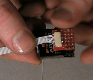
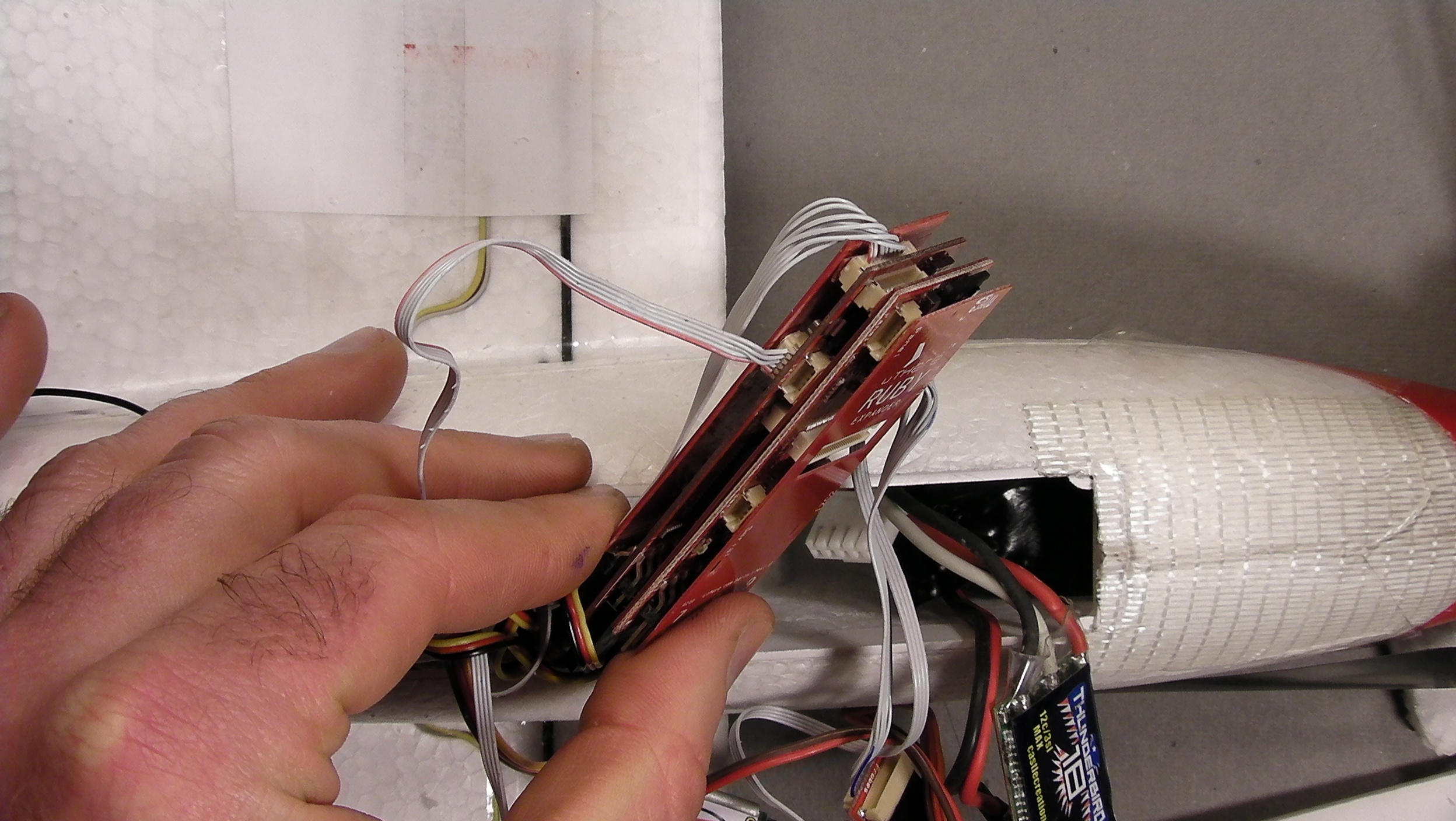
| The best way to insert a small ribbon cable plug is to gently insert it slightly into the receptacle just enough to line it up (you can hold it by the wires), then press firmly into place by pushing something like a butter knife or wide screwdriver blade against the plastic at the back of the plug. Don't try to use your fingernail, because the wedging action of your fingertip may pry the controller's cover off. |
|
Before proceeding further, this is a good time to review connections and polarities, turn on your transmitter, apply power to Ruby, and make sure Ruby and everything else is working correctly.
Beware the Ruby-controlled propeller. [See warnings]
If the Expander is attached, the red and green lights should flash alternately for a few seconds when power is applied, then the red and/or green light should blink in various patterns to indicate whether plane and autopilot are ready for flight. (Green light by itself means everything is OK including GPS lock, battery voltage, and receipt of good signal from your transmitter, but GPS lock might be difficult if you are testing indoors, so you'll more likely see red flashing light.) |
 |
Inserting the Ruby Controller
Now, unplug the battery and insert Ruby into the payload area..
Instead of using Velcro, simply wedge the Ruby controller into place by inserting a piece of foam between it and the opposite fuselage wall. (EPP foam is best. A small block was included with your Merlin kit. A razor saw is the best tool to cut it to the right thickness.)
Be sure that the controller is lined up with the longitudinal axis of the plane. This orientation is critical for proper IMU operation. The controller should be pressed flat against the fuselage wall, with no cables stuck between to misalign it. The bottom edge of the controller should line up with the edge of the plastic hatch opening. |
click to enlarge |
Inserting the Battery and ESC
We've found that it's best to insert the battery into the front of the plane BEFORE inserting the ESC and motor current sensor.
It's easiest to insert a larger battery if you orient the battery so that the corner from which the leads come out face the bottom aft of the plane. You can then hold the battery by the leads, and pivot it into place around the lip of the payload bay door.
Be sure that the wires leading from the ESC to the motor are pressed against the top of the payload area by the battery so they don't rub against the spinning motor.
Spin the motor/prop to be sure that the battery is not pressed up against the back of the motor and it can turn freely.
Wedge a piece of foam between battery and payload wall if necessary to keep it from shifting during flight.
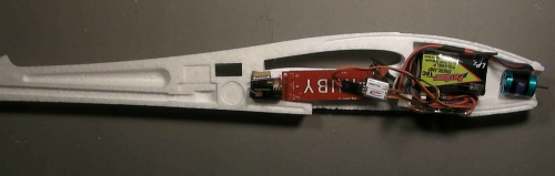
The ESC and motor current sensor can be tucked in on top of the rear half of the battery, just underneath the hatch door.
.. and you should be left just enough room to tuck the power connector after you've plugged it into the battery.
Aaaargh!
Getting everything to fit in the Merlin can take a little practice. Don't forget that there are some [videos] that you can watch to see it done. |
|
| |
Balance
Proper balance is critical for any aircraft. Although Ruby's "fly by wire" capability may (or may not) be able to bring an unstable plane under control, it will still fly very poorly without radical changes of settings away from standard default values, and excessive servo activity. Most notably, if the plane is a little tail heavy, Ruby control of pitch and airspeed will be erratic with standard settings, and if it's too tail heavy, the plane will be completely uncontrollable with any settings. If too nose heavy, you won't be able to fly at slower airspeeds needed for soft landing.
With all components in place as they will be in flight, support the Merlin with fingers or pivot points placed on the black wing spars.
If the plane noses up, move components inside the payload forward, choose a heavier battery, or add weight to the forward payload compartment.
If the planes noses down, move components inside the payload aft, add weight to the tail, or choose a lighter battery.
We have used batteries ranging from 500 to 880 mah in the Merlin with Ruby. |
| |
Making modifications (or not)
We don't recommend modifying the Merlin substantially, particularly if the modification involves extra weight or drag. It's too small for most FPV gear. Complaints have been posted to forums about a tendency of the Merlin to irrecoverably "tip stall", but we suspect that in most, if not all cases, excessive drag or weight / wingloading are the cause. Indeed, one posting was accompanied by a FPV video taken from the Merlin. In many hours of testing the Merlin in a "stock" configuration, we've never encountered such behavior. |
| |
Transmitter settings and trim
If you have a Spektrum transmitter such as the DX-8 that can save and load settings to a ".SPM" file SD Flash chip, please see the Merlin + Ruby SPM file for Spektrum transmitters.
Otherwise, you'll need to follow these instructions:
In the standard configuration, Ruby is expecting you to have "flaperon" mode enabled in settings so that aileron control will be output on Ruby's "6 Ail L" and "2 Ail R" servo outputs. Contact support@uthere.com if your transmitter doesn't support "flaperons" / dual ailerons and you need a configuration for a single aileron channel.
On most transmitters, you will normally have to reverse the elevator and both aileron channels (Spektrum channels 2, 3, and 6) for correct direction on the Merlin. Rudder channel is left unreversed.
If your ESC has "braking", program in "hard" braking to cause the propeller to fold rather than "windmill" when throttle is closed. This will give much better gliding performance.
Ruby performs best, particularly at near-stall airspeeds, if it's able to make fullest possible movements of control surfaces when necessary. The Merlin is an extremely responsive plane, however, so big throws can make it almost impossible to fly without exponential mixing. If you have a transmitter that has exponential mixing, attach control rods as far out on servo horns as possible for maximum throws, and set aileron and elevator to about 65% exponential so that the plane is more easily controlled by you in manual mode.
If you don't have a transmitter with exponential mixing, stay with the more conservative control rod positions recommended by the manufacturer. Ruby will still perform well, and this will ensure that the plane is easy to fly manually. |
|
Configuration
Now that Ruby is physically installed, you'll need to load configuration settings to match your airframe, receiver, and preferences if your Ruby was not shipped pre-configured for you.
Please proceed to configuration.
|
|


